Sunday, 26 May 2013

Universal Cross Joint

The part that I am going to learn today is the Universal Cross Joints. I was given a 2-pieces driveshaft with cross joints and the Servicing Driveline Units practical instructions manual.

Image of a 2-piece driveshaft with universal cross joint.


I began with checking on the phasing of the yoke, the shaft's runout and the movement of the cross joint. Making sure that every pieces of metal is straight, damage free and even rust free.
Image of checking driveshaft's runout with a DTI gauge.


Then I started to take the shaft apart by resting it on a vice, and slightly tapping the area below the yoke with a ball-pein hammer to make the joint cap pop out from the yoke. I rotated the yoke and removed the caps one by one. And then I found out that 3 out of 4 clirclips on each caps went missing, the remaining 1is in a very bad condition and needs a new replacement. There are also short of needle rollers inside the caps.

Image of yoke, cross, o-ring, caps, needle rollers and cir clip.


I would have replaced the joint if I was in a workshop as the issue of missing circlips and needle rollers are the sign of the universal joint getting worn out in long run and it may cause squeaking and grinding sounds when the car is moving.


Tripod Joint, CV Joint and Clutch

After missing out a few morning practical classes due to the early arrival of my daughter. I came in on the last day of second week eventually to finish off the remaining items with some helps and guidances from my classmates.

Tripod Joint
Also known as inner CV joint, consists of housing and spider assembly. Has 3 needle bearing rollers on the spider that can slide inside the housing with 3 roller channels. This allows the tripod joint to slide back and forth, enabling the driveshaft to extend when the angle changed due to suspension movement, to create a smoother ride on an uneven surface.
Rollers on the spider of a Tripod Joint.

The image of a spider assembly.


CV Joint
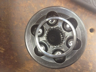
CV joint is located between the driveshaft and the wheel. Unlike the tripod joint, CV joint is fixed and cannot be extended. It is used to transmit the power from transmission to wheels at constant speed, and ease off the pressure on driveshaft when the suspension moved. The most common type CV joint is Birfield CV joint, it consists of balls, ball cage, inner race with splines and outer housing with a short axle. Usually a CV joint can last for a very long period of time, apart from it's rubber boot. The boot splits and perishes from time to time and needs new replacement otherwise the CV joint will fail and create a clicking noise when turning.
The components of a CV Joint.

The assembly inside the housing of CV Joint.


Image showing the sign of crack of a rubber boot.


Clutch
Clutch is used to engage or disengage between moving objects. It can be found in between the engine and transmission in most of the manual car. A clutch disc is in the middle of the engine flywheel and pressure plate that bolted to the flywheel. When the cone-shaped diaphragm spring is pressed against the pressure plate, the clutch disc is also being squeezed against the flywheel. The friction on the clutch disc is holding the plate and flywheel together, this cause the engagement of the engine and the transmission and make them spin together at the same speed.

When the driver put his foot down on the clutch pedal, the release bearing is being pushed towards the centre of the diaphragm spring causing the spring to distort and pull away the pressure plate from clutch disc to release the clutch free.

Clutch needs to be installed correctly to prevent 'slipping' or 'sticking' problem. The clutch will start to slip when the surface of the clutch disc is worn out and the friction on the disc is damaged. This will stop it from transmitting power to the wheels. When it does not release and keeps sticking to the flywheel, it will stop the car from going into gears.

The pressure plate assembly of a clutch.

The flywheel at the end of the engine.


Image of a clutch disc or friction disc.


Thursday, 9 May 2013

Manual Transmission - Part 3

Shane and I have finished re-assembling the transmission yesterday. I got plenty of time this morning to work on my practical workbook while waiting for the lecturer to show us the DTI.

Just about an hour before the class end, the demonstration began. The lecturer bolted the steel angle plate onto the body of transmission. Then magnetised the DTI gauge on the steel plate. He placed the point on the 5th gear and pressed the gear down. He adjusted the gauge reading to zero and then lifted the gear up. The highest and lowest readings have been recorded, subtracted and multiplied by 0.01 as per the scale of the DTI gauge.

We have been told that we will often use DTI on engine, seems like there are many clearances that we need to be aware of under the hood.

Image of Dial Test Indicator being used for measuring the 5th gear thrust clearance.

Wednesday, 8 May 2013

Manual Transmission - Part 2

I continue with calculating the gear ratio on day 2 for gear 1 to 5 as well as the reverse gear. The formula applied is driven over driver:

                       driven gear teeth
Gear ratio =                                
                       driver gear teeth

For example:


Gear ratio = 30 / 60
                 = 0.5 : 1

And for reverse gear, I have ignored the reverse idler gear and used just the gears on the input and output shafts for the calculation of gear ratio because of a couple of reasons:

a) The purpose of reverse idler gear is only to change the direction of the driven gear.
b) For multiple gear calculations, the result will be the same if the following formula is applied:


                       driven gear teeth            driven gear teeth
Gear ratio =                                    x                                   
                       driver gear teeth             driver gear teeth


I then moved on to measure the thrust clearance of the gears. Well, this is when the feeler gauge comes in place. I pushed the gear to the most upward and downward on the shaft and measure the biggest and the smallest gap it has by inserting the different thickness of steels of the feeler gauge into the gap. Then added up all the numbers in millimetre (mm) that marked on the steels for both the biggest and smallest gap, subtracted them to get the answer for thrust clearance for each gear to ensure there meet with the manufacturer specifications.

I have just learnt about thrust clearance today and I would like to talk a little bit more about it because it is essential in most of the mechanical parts assembly. Thrust clearance is a gap or distance in between two or more moving objects, it's purposes are to provide space for lubricating oil, thermal expansion, manufacturing tolerances and objects distortion to minimise wears or damages from the engagement of moving objects in long run.


Tuesday, 7 May 2013

Manual Transmission - Part 1


Today is the first day of my Transmission and Driveline course. When the class begin, my lecturer paired me up with my classmate Shane to work on a gearbox. We been given the transmission practical workbook and service manual, then I started to realise that the most important things that I need are not with me -- my tools! But fortunately, Shane has brought his today. And I don't have to end up either just sit there watching other students doing their works or running up and down borrowing tools from others. And yes, lesson number one I have learnt today, always bring my tools with me regardless where am I, as a mechanic.

We started to dismantle the gearbox step by step by following the instruction from the service manual after a pre-dismantle check. We skipped measuring the trust clearance for 5th gear as we only have one working Dial Test Indicator (DTI) left, and the lecturer will demonstrate the setup and the use of it on one gearbox the next day or so to the whole class. This was my first time using the puller and a special tool with a big round synchro teeth head with long handle. The special tool was used to hold the 5th gear fixed synchro hub, and then the 5th gear was pulled out from the transmission with a puller and spacer. And also another type of 'clamp' lookalikes puller being used to pull off the 5th gear fixed synchro hub. 

I get to know and seen many different types of components in the transmission during the process of dismantling it, like the detent mechanisms, the selector shafts, reverse shift bracket and so on. The thing that interest me the most was the interlocking mechanism of  the 5th- reverse shaft and 3rd-4th selector shaft. There is an interlocking ball in the hole of the bracket that will move in between both shafts and it will lock one of the shaft from moving when the ball slide into the groove of that particular shaft. For example, if I wanted to pull and remove 3rd-4th selector shaft and it jammed, the interlocking ball might sit in the groove on the shaft stopping it from moving. I will have to lift and hold the 5th-reverse shaft for it's groove to be on the same horizontal level so that the ball can slide over and free up the 3rd-4th selector. 


I then counted the gear teeth for gear 1 to 5. I found it easier to mark 1 teeth with liquid paper to start with, and then mark again when I counted to 20 and so on and so forth. And I managed to count all the gears just before the first practical class finished for the day.